Utility-scale battery storage is expanding rapidly. The U.S. Energy Information Administration reported in August 2026 that operational battery storage capacity reached nearly 52 GW in the first half of the year after averaging 70% annual growth over the previous three years.
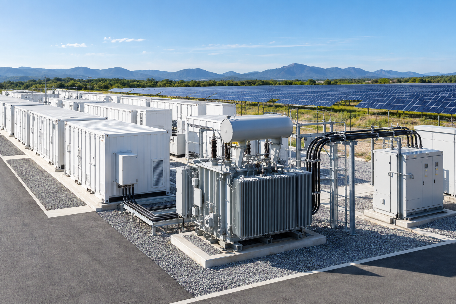
For electrical equipment buyers, this growth creates a specific engineering challenge: a battery energy storage system does not load its transformer in the same way as a conventional one-direction industrial load. Charging and discharging cycles, inverter harmonics and repeated changes in power flow must be considered together.
Why BESS Duty Is Different
A battery project may import power while charging and export power while discharging. The duty cycle can change several times per day, and operating strategies may be adjusted according to electricity prices, grid services or renewable generation. The transformer therefore needs to be evaluated for bidirectional loading, cyclic thermal performance and the actual inverter operating profile.
Inverter-based systems can also introduce harmonic currents and voltage distortion. These do not automatically make a project unsuitable for a standard transformer, but they do require the supplier to review loss calculations, temperature rise, insulation stress, audible noise and any derating that may apply.
Six Items to Put in the Transformer Specification
Power and energy profile: provide maximum charge and discharge power, expected duration, daily cycles and overload requirements.
Voltage and grounding: confirm inverter-side and grid-side voltage, vector group, neutral arrangement and grounding method.
Harmonic data: share the expected current spectrum and total harmonic distortion from the power-conversion system.
Impedance and fault duty: coordinate transformer impedance with fault levels, protection settings and the inverter manufacturer’s requirements.
Environmental conditions: state ambient temperature, altitude, enclosure, corrosion class and any fire-safety or fluid requirements.
Monitoring: define winding and oil temperature, pressure protection, cooling status, alarms and communication interfaces appropriate to project criticality.
Co-Located Solar and Storage Need Coordinated Design
EIA data show that many large battery systems are located with solar plants. Shared connection infrastructure can reduce project cost, but the transformer rating cannot be selected by simply adding solar and battery nameplate values. Engineers need a realistic simultaneous operating envelope, including whether the battery charges from solar, from the grid or from both.
The collector system, switchgear, cables, protection and main step-up transformer should be checked as one package. A transformer sized only for the initial operating mode may become a bottleneck when the plant later changes its charging strategy or expands its storage capacity.
Plan for the Operating Strategy, Not Only the Nameplate
The most reliable quotation starts with a clear single-line diagram and an operating profile agreed by the battery integrator, inverter supplier and grid-connection engineer. Early coordination allows the transformer manufacturer to confirm temperature rise, losses, insulation level, impedance and accessories before production capacity is reserved.
Là một thiết bị quản lý phân phối điện phổ biến, cầu dao là thiết bị không thể thiếu trong hầu hết các khu vực tiêu thụ điện. Cùng với sự phát triển không ngừng của thành phố, các loại cầu dao cũng liên tục được cải tiến. Với sự phát triển của Internet vạn vật (IoT)...
Biến tần quang điện là một bộ phận quan trọng trong hệ thống phát điện quang điện, có chức năng chính là chuyển đổi dòng điện một chiều do các mô-đun quang điện tạo ra thành dòng điện xoay chiều. Biến tần không chỉ có chức năng chuyển đổi trực tiếp sang dòng điện xoay chiều, mà còn...
Nhu cầu điện toàn cầu đang tăng nhanh trong giai đoạn 2026–2027. Hãy tìm hiểu lý do tại sao hiệu suất máy biến áp, công suất lưới điện, việc xác định thông số kỹ thuật sớm và quy hoạch phối hợp hệ thống thiết bị đóng cắt lại quan trọng đối với các dự án điện mới.
Trước khi lựa chọn thiết bị cho dự án của bạn, hãy so sánh các loại máy biến áp khô và máy biến áp ngâm dầu dựa trên các tiêu chí như hệ thống làm mát, lắp đặt, bảo trì, an toàn phòng cháy chữa cháy, hiệu suất và ứng dụng.
 Các danh mục nổi bật











Gửi yêu cầu tư vấn về sản phẩm
Chúng tôi sẽ liên hệ với quý khách trong vòng 24 giờ